


How do I handle or carry a QCL?
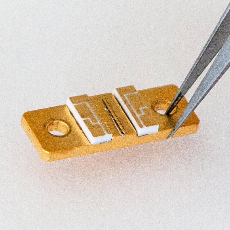
The most delicate parts of a QCL are the laser chip itself and the bonds connecting it to the ceramic pads. Therefore the QCL should be touched only at the copper carrier (far from the laser chip and the bonds), or at the ceramic pads (again away from the bonds).
To insert it into or to take it out of the Starter Kit housing, gently grab the ceramic pad from above with fine tweezers, and whenever possible, carry the QCL placed flat on a stable surface. Take special care not to touch bonds nor the laser chip itself, since this can immediately destroy the QCL. More detailed instructions can be found in §7.1 of the manual.
The two most important things to keep in mind are:
- Avoid contact of the front facet of the QCL with any object (like the walls of a box where it is stored).
- Never allow water droplets to condensate on the QCL.
What are the allowed pulse lengths for a pulsed QCL?
Pulsed QCLs are delivered with a datasheet. Typically, lasers are tested using 300 ns pulse lengths. Shorter pulse lengths may be possible but the laser’s response will depend on its impedance which can be affected by housing, cables and other external elements. The shortest pulse length achievable with a S-2m driver is 10 ns, but the risetime can be in the range 5-15 ns making the shortest pulses not recommended.
Longer pulse lengths will heat up the laser and cause chirp within the pulse and a decrease in peak power. If you intend to use longer pulse length, this should be specified at the time of purchase. A special datasheet can be produced.
Using a laser with pulsed lengths longer than specified in the datasheet is liable to void the warranty.
If you wish to take the risk, a good method is to use a fast detector (e.g. a MCT detector) and slowly increase the pulse length. The maximum workable pulse length will be the length at which the instantaneous power at the end of the pulse is 50% of the power at the beginning.
What are the allowed pulse lengths for a CW QCL?
A CW QCL is tested only with continuous excitation, where any pulse longer than one millisecond is seen as “continuous”. The performances shown on the datasheet are the performance in the steady state and do not consider transient effects that occur in this first millisecond. It is also possible to use pulsed excitations of any shorter length on these lasers bearing in mind that:
- The wavelength at the beginning of the peak will be shorter than the CW wavelength
- The signal will show chirp
- The strength of the chirp can vary from one laser to another
- There is no guarantee that the laser is single-mode with short pulses
What is the distance from the laser facet to the ZnSe window in a LLH?
The window thickness is 2.0 +/- 0.1 mm. The laser facet is 4.5 +/- 0.5 mm from the exterior facet of the window and 2.5 mm +/- 0.5 mm from the inside facet. The window is 1.0 +/- 0.2 mm recessed from the front of the LLH.
How can I read the voltage output of the laser from the connection 5 and 6 of the LLH?
What is the linewidth / frequency noise of a QCL?
The instantaneous linewidth of a QCL can be extremely low, of the order of kHz.
In practice however, the total noise of a system will almost always be given by the noise of the current driver and/or the temperature noise, and when that noise is much higher than the intrinsic noise you can consider the QCL as a perfect transducer and compute the effective amplitude or spectral noise from the datasheet.
Do QCLs suffer from optical feedback?
What type of chiller should be used to cool the LLH?
That being said, using a flow rate of 0.3 l/min of water kept at a temperature in the 15°C-20°C range should be sufficient for most practical purposes.
What type of cooling is needed for the HHL?
There are two sources of heat in a HHL: the heat created by the laser itself, which can be read from the datasheet, and the heat created by the TEC which is equal to its power consumption and depends on the temperature differential between the laser chip and the baseplate of the HHL. The sum of these can reach up to 40W and must be dissipated away from the baseplate. Typical specifications require the baseplate to be kept at a temperature of 20°C.
While it is in every case required to connect the baseplate to a heat sink, different types of heatsinking methods can be used, from passive cooling to air cooling to water cooling. The HHL is designed to allow maximum flexibility in your system design by providing a minimal flat interface.
It should be noted, however, that only the bottom baseplate is directly heated and designed to be connected to the heat sink. It is not recommended nor useful to attach anything to the top plate of the HHL.
Can I solder a laser submount?
To protect the coatings on the lasers and avoid melting the indium solder used on some submounts, it is not recommended to heat the submounts to temperatures higher than 100°C, even temporarily.
I cannot connect the S-2 driver using the supplied software
The supplied control software is not fully a driver but a control panel that allows you to access the hardware. Access to this hardware must be allowed by your computer system in order to use it. Such access may depend on your particular system and Alpes cannot guarantee the correct working of your computer. Nevertheless, if you cannot see or use the ports you can follow these general guidelines:
- Is the red LED light on the board (visible if you use the OEM version without protective box) lit? If it is not, check the power connection.
- If you use the USB-to-serial adapter, while normally this device is automatically recognized by most distributions it could be not yet installed on your machine. You can download the drivers at http://www.ftdichip.com/Drivers/VCP.htm; follow the instructions on the site.
- Under linux if libraries are missing installing libxcb-xinerama0 (through apt-get) should help
- If you can see the correct port but the connect button does not work, you may not have access to the port. Launching the software with admin rights (i.e. using sudo under linux) may help.
Why is the datasheet of the laser different from the one I picked from the website?
The datasheets shown on the website are measurements taken on submounts. When the laser is encapsulated, the submount is soldered directly onto the thermoelectric cooler, sometimes improving thermal performance. A new measurement is taken immediately prior to shipment with the final performance.
What is the typical lifetime of a QCL chip?
Once in a while, some lasers are selected for long-time testing. Some have been tested for up to 32’000 hours of continuous operation at Alpes with no degradation of maximum performance. This external study has operated various types of QCLs for over 1.5 million device-hours and has found that the mean time to failure of quantum cascade lasers operating at a heat-sink temperature of 25°C is expected to be 809’000 hours or 92 years of continuous operation. Furthermore, Alpes users have reported operating lasers in the field for extended periods of time. A specific example can be found in this paper which describes an experiment that ran for 4 years uninterrupted with no degradation in performance.
In addition to the laser chip MTTF, a typical laser package contains other parts that can degrade with time. In particular, the Peltier cooler will see its performance degrade with time and the coldest reachable temperature will slowly increase. Furthermore, the soldering of the chip to the submount may degrade which will affect the effective temperature of operation to reach a specific wavelength. These effects are slow and can be reversed by re-encapsulating the chip if the specifications are no longer reached within the warranty period. By design, packaged lasers should remain within their specifications for up to 5 years.
What is the polarization of my laser beam?
The emission from a QCL is always polarized linearly with the electric field perpendicular to the layers (and the copper sub mount) because the intersubband transition exhibits a quantum mechanical selection rule. With the copper submount or the bottom of a HHL on a table, the light is emitted with vertical polarization. In an external cavity laser kit, the chip is mounted vertically, so the polarization output is horizontal.
For ICL however the electric field is always parallel to the layer, so the emitted field is horitontally polarized for submounts or HHL and vertically polarized in external cavity laser kits.
What is the spatial mode of my laser beam?
All of our stock lasers have a single spatial mode. The mode is typically the Gaussian TEM00 mode. If this is a specific requirement in your application, please be certain to ask for a mode measurement as spatial modes are not automatically specifically measured.
What is the divergence of my laser beam?
The unipolar laser is designed around a tightly confined waveguide. For this reason, the beam diffracts strongly at the output facet and has a (full) divergence angle of about 60 degrees perpendicular to the layer and 40 degrees parallel to the layers (see figures below). A f#1 optics will typically collect about 70% of the emitted output power for a laser on submount or in a LLH housing. Be careful that the collected output power will decrease with the square of the f-number of the collection optics.
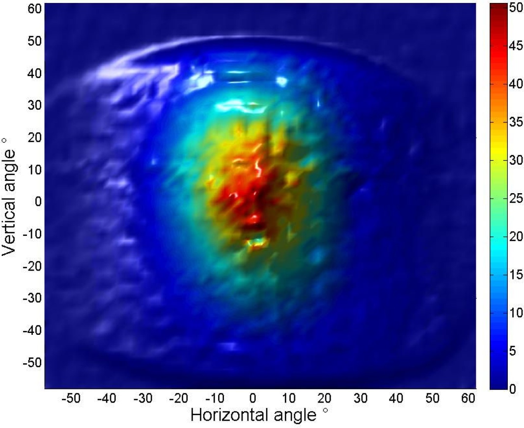
of an uncollimated QCL.
Our TO3-L and HHL-packaged QCLs are collimated with a high numerical aperture (NA = 0.85) aspherical lens to maximize collection efficiency. The beam diameter is ≤ 4 mm at the output of the package and the full-angle beam divergence at 1/e^2 is ≤ 6 mrad for HHL (higher for high power devices) and ≤ 10 mrad for TO-3. A beam picture of a typical collimated QCL emitting at a wavelength of 8 µm is displayed below, showing the good beam quality.
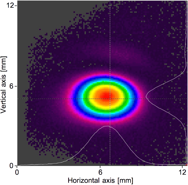
Typical beam profile
of a collimated QCL.
What International and global policies are followed by Alpes Lasers?
Is Alpes Lasers compliant with ISO standards?
Alpes Lasers Aerospace Defense Systems QCL Products conforms to the BS EN ISO 9001:2015 and EN 9100 : 2018 standards, which are Technically equivalent to AS9100D. You can find the certificate here.
Modulation schemes overview
Requirements
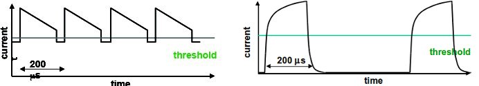
Ramps
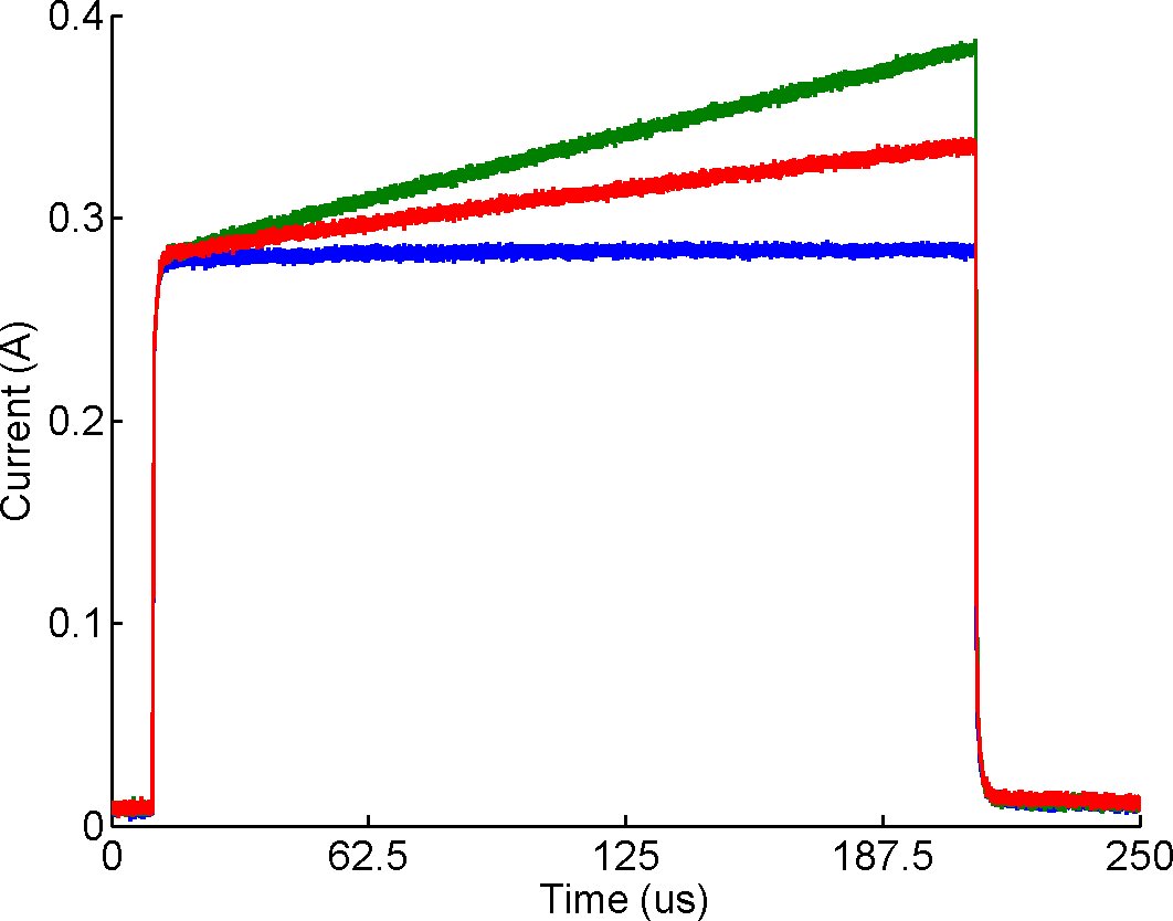
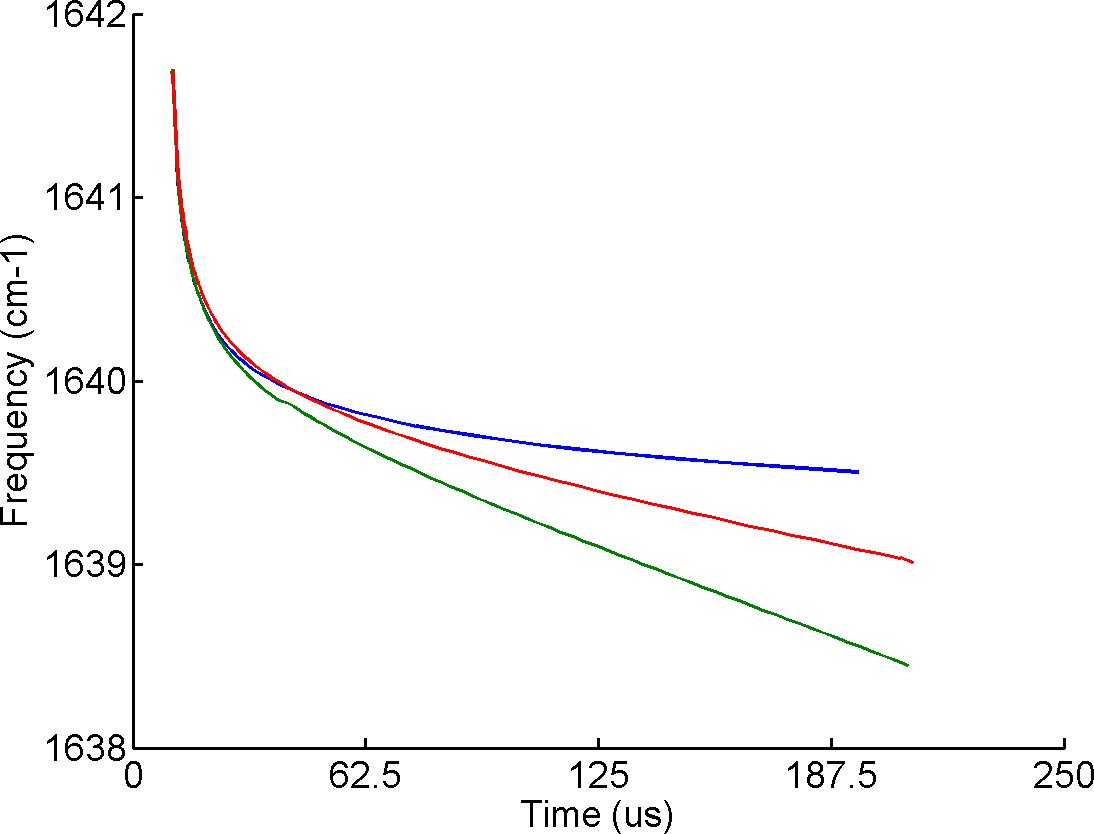
Parameter Dependency
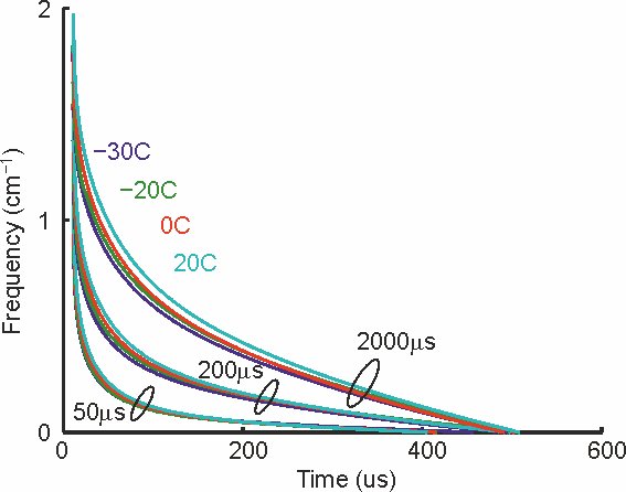
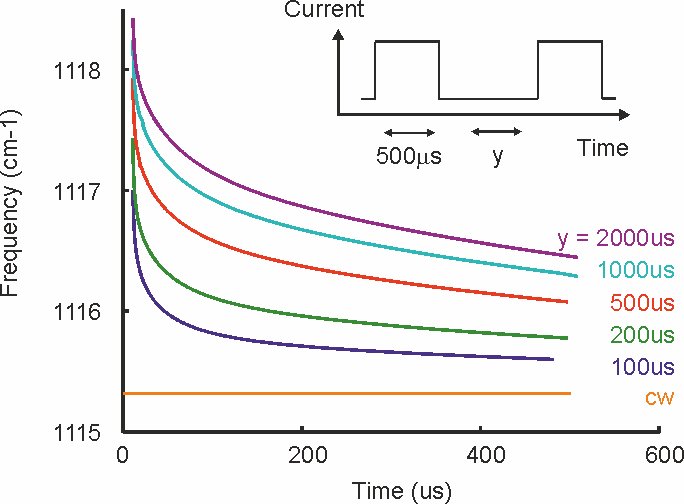
The tuning endpoints and the tuning rate are both dependent upon the duty cycle. The image to the left shows absolute tuning with respect to duty cycle. As the pulse-to-pulse separation becomes smaller, the behavior approaches the monochromatic CW result.
Click to enlarge
Hardware solutions
Alpes Lasers has also developed a driver fully dedicated to running lasers in the slow-chirp mode.
An application note is available outlining the performances of the driver in a specific spectroscopic application of nitric oxide detection.